r-pi-gpio
A high performance, memory mapped, Node.js API for GPIO on the Raspberry Pi.
![]()


Getting Started
Installation
npm install r-pi-gpio --saveIntegration
var gpio = ;API
gpio.init(callback)
Creates the memory mapping with a device-specific memory offset.
You must call this function only once and before any other function.
gpio;gpio.createInput(pin)
Creates a new GPIO input function and returns it.
var input = gpio;input()
Returns true if the input voltage level is high, and false otherwise.
var level = ;gpio.createOutput(pin)
Creates a new GPIO output function and returns it.
var output = gpio;output(level)
Sets the output voltage level to high or low.
;;Example
This example needs access to the physical memory, so it must run as root.
sudo node examples/onoff.js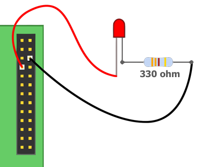
A quick word about the electronics involved. LEDs are Light Emitting Diodes and the diode part is important for us – they only pass electricity one way, so we need to make sure we put them in the right way round. They have a long leg and a slightly shorter leg. The long leg goes to the plus side and the shorter leg to the negative (or 0v) side. If we’re cut the legs short (as I have done here), then another way is to look at the side of the LED – there will be a flat section. Think of the flat as a minus sign and connect that to the 0v side of the circuit.
If we allow too much current through the LED, it will burn very bright for a very short period of time before it burns out, so we need a resistor to limit the current. Calculating the resistor value is not difficult but for now, just use anything from 270Ω to 330Ω. Anything higher will make the LED dimmer.
Raspberry Pi GPIO Pin Layout
Raspberry Pi Model A/B (Rev 1.0)
| Assignment | Pin | Pin | Assignment |
|---|---|---|---|
| 3.3V | 1 | 2 | 5V |
| GPIO 0 (SDA0) | 3 | 4 | 5V |
| GPIO 1 (SCL0) | 5 | 6 | GROUND |
| GPIO 4 | 7 | 8 | GPIO 14 (TXD0) |
| GROUND | 9 | 10 | GPIO 15 (RXD0) |
| GPIO 17 | 11 | 12 | GPIO 18 |
| GPIO 21 | 13 | 14 | GROUND |
| GPIO 22 | 15 | 16 | GPIO 23 |
| 3.3V | 17 | 18 | GPIO 24 |
| GPIO 10 (SPI_MOSI) | 19 | 20 | GROUND |
| GPIO 9 (SPI_MISO) | 21 | 22 | GPIO 25 |
| GPIO 11 (SPI_SCLK) | 23 | 24 | GPIO 8 (SPI_CE0_N) |
| GROUND | 25 | 26 | GPIO 7 (SPI_CE1_N) |
Raspberry Pi Model A/B (Rev 2.0)
| Assignment | Pin | Pin | Assignment |
|---|---|---|---|
| 3.3V | 1 | 2 | 5V |
| GPIO 2 (SDA1) | 3 | 4 | 5V |
| GPIO 3 (SCL1) | 5 | 6 | GROUND |
| GPIO 4 | 7 | 8 | GPIO 14 (TXD0) |
| GROUND | 9 | 10 | GPIO 15 (RXD0) |
| GPIO 17 | 11 | 12 | GPIO 18 |
| GPIO 27 | 13 | 14 | GROUND |
| GPIO 22 | 15 | 16 | GPIO 23 |
| 3.3V | 17 | 18 | GPIO 24 |
| GPIO 10 (SPI_MOSI) | 19 | 20 | GROUND |
| GPIO 9 (SPI_MISO) | 21 | 22 | GPIO 25 |
| GPIO 11 (SPI_SCLK) | 23 | 24 | GPIO 8 (SPI_CE0_N) |
| GROUND | 25 | 26 | GPIO 7 (SPI_CE1_N) |
Raspberry Pi Model B+ / Raspberry Pi 2 Model B
| Assignment | Pin | Pin | Assignment |
|---|---|---|---|
| 3.3V | 1 | 2 | 5V |
| GPIO 2 (SDA1) | 3 | 4 | 5V |
| GPIO 3 (SCL1) | 5 | 6 | GROUND |
| GPIO 4 | 7 | 8 | GPIO 14 (TXD0) |
| GROUND | 9 | 10 | GPIO 15 (RXD0) |
| GPIO 17 | 11 | 12 | GPIO 18 |
| GPIO 27 | 13 | 14 | GROUND |
| GPIO 22 | 15 | 16 | GPIO 23 |
| 3.3V | 17 | 18 | GPIO 24 |
| GPIO 10 (SPI_MOSI) | 19 | 20 | GROUND |
| GPIO 9 (SPI_MISO) | 21 | 22 | GPIO 25 |
| GPIO 11 (SPI_SCLK) | 23 | 24 | GPIO 8 (SPI_CE0_N) |
| GROUND | 25 | 26 | GPIO 7 (SPI_CE1_N) |
| ID_SD | 27 | 28 | ID_SC |
| GPIO 5 | 29 | 30 | GROUND |
| GPIO 6 | 31 | 32 | GPIO 12 |
| GPIO 13 | 33 | 34 | GROUND |
| GPIO 19 | 35 | 36 | GPIO 16 |
| GPIO 26 | 37 | 38 | GPIO 20 |
| GROUND | 39 | 40 | GPIO 21 |
Related Links
- RPi Low-level Peripherals
- BCM2835 ARM Peripherals
- GPIO Examples - A single LED
- Standard Resistor Values
- Pull-up and Pull-down Resistors
Running Tests
To run the test suite first install the development dependencies:
npm installthen run the tests:
npm test